The 2nd Multiband compressor can be used in many ways, for example to fine-tune the output of the first, or to add some density.
Because the first Multiband Compressor can be used in both Analog and Digital mode and this one only supports Analog mode, to keep the descriptions clear, for the first Multiband Compressor the Digital mode parameters are described, and for this one the Analog parameters are explained. Main panel General compressor/limiter settings.
Enabled Turns the compressor/limiter on.
Quick adjust panel Achieve several effects with a single slider.
Most of these sliders impact the value of several other sliders that are described below, to achieve a certain effect.
Density Makes attack and decay faster or slower. Sound is more squashed.
This slider adjusts both attack and decay to have more aggressive compression.
Works on all bands simultaneously.
Aggressiveness (hot) Makes attack and decay faster or slower. Sound is more squashed.
This slider adjusts both attack and decay to have more aggressive compression.
Works on all bands simultaneously.
Main levels panel Controls at which input level the compressor and limiter become active.
Drive Amplification of the input before the compressor/limiter.
Output level Amplification of the output level after the compressor and limiter.
It is generally a good idea to make sure that the output level of each filter is set such that disabling the filter does not change the level. This makes it much easier to compare what each filter does (it can be turned on and off without having to adjust other settings).
Attack Times multiplier Value with which to multiply all Attack Time.
Release Times multiplier Value with which to multiple all Release Time.
Median display panel Displays the median attenuation value of compressor bands.
If the median amount of attenuation of each band of the multiband compressor is roughly equal, then soft and loud sounds are handled roughly the same.
On some radio stations, you can clearly hear that when a song ends and fades out, the frequency content shifts. This happens because at some point some frequencies are still being compressed while others are not, or no frequencies are compressed anymore and the sound is identical to the input.
That by itself is fine, but if the multiband compressor changes the sound of the input, not by using Band mix but by modifying compressor settings such as Threshold level and Ratio, then this type of problems start to occur.
If you configure the multiband compressor such that on average, after playing a lot of differnt program content through it, all bands have the same amount of compressor action, then this will not or hardly happen (only for songs that sound very different from the average).
The median display shows dotted bars in the multiband compressor attenuation meters, so you can run a few hours of programming through it and then check if they look fine - and adjust some levels if needed.
Reset median calculation Throws away all the historic median data and starts to measure anew.
Hide median display Removes the median displays.
Also slightly reduces the CPU load.
Bands panel Controls the number of multiband compressor bands.
Bands The number of bands.
If you change the number of bands, all the Frequency and RMS block size sliders will get new default values. A popup will ask you if you want to update the sliders to these new default values.
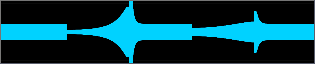
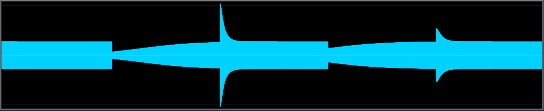
Flat frequency response panel This slider helps to keep the frequency response of both sweeps and pink noise flat.
If you play a sweep through a multiband compressor, it happens frequently that the output is louder in some places than in other. Usually, it is louder around the crossover frequency between bands, although this also depends on the amount of compression.
A good value for Flat Frequency Response can only be found by trial and error, the value that gives the flattest response on sweeps should be used. It is generally also a good idea to test the response for pink noise; this slider has very little effect on pink noise but it should be flat as well, except for intentional non-flatness.
Update: With properly setup band frequencies, this slider is not needed. The default frequencies in Stereo Tool have not yet been adjusted for this. But they will be in the future, making this slider useless for most users.
Flat frequency response The flatness value.
0 does nothing, 100% moves the measurement strength at crossover frequencies from -6 dB to 0 dB. See the thin lines in the Bands display.
Flat band tops Changes the shape of multiband processing bands.
This enables a different band splitting mode with flatter top areas of the different bands, and a different mechanism to keep the frequency response flat.
The advantage of this is that bands have less impact on each other, which can be used to generate a more stable sound image.
Compatibility mode (bad) Compatibility option for older presets.
There was a bug in the implementation of Flat Frequency Response, older presets might depend on it. Don't use this for new presets!
Wideband Gate panel Gate that effects all bands.
Similar to Release Gate, but based on the total input, and it affects all bands simultaneously.
Band coupling panel Controls coupling between adjacent multiband bands.
To avoid very extreme effects from the multiband compressor if certain frequency ranges are nearly absent or very loud in the incoming signal, the bands can be tied together to stop a single band to move very far away from the adjacent bands.
Band coupling Coupling between all bands.
This number defines how strongly bands are coupled if they are exactly one octave apart (Frequency doubles between bands). Bands are coupled stronger if they are closer together and weaker if the distance between them is bigger.
Only pull down Pull bands down if adjacent bands are lower, but never pull bands up.
This gives better level control.
Low Freedom Ignore coupling for the lowest band.
The lowest band is somewhat special: If you don't allow it to move freely, absense of bass or presence of very strong bass cannot be handled properly. On the other hand, if you want the output to stay true to the original, that's actually a good thing.
With this slider you can determine how much of band coupling is ignored for the lowest band. Note that since bands are still coupled in both directions, the changed value of this lowest band will also have some effect on adjacent bands.
High Freedom Ignore coupling for the highest band.
The highest band is somewhat special: If you don't allow it to move freely, absense of highs or presence of very strong highs cannot be handled properly. On the other hand, if you want the output to stay true to the original, that's actually a good thing.
With this slider you can determine how much of band coupling is ignored for the highest band. Note that since bands are still coupled in both directions, the changed value of this lowest band will also have some effect on adjacent bands.
Band linking panel Controls band linking between adjacent multiband bands.
The idea is similar as Band coupling, but the type of coupling is very different. One of the things that can easily be done with Band Linking is to ensure that the lowest band doesn't get attenuated less than band 2, which helps to avoid 'thunder bass' during voices, and to ensure that the highest band doesn't get attenuated less than the band before that, which avoids too much of the highest highs, which can sound unnatural.
Non-linear
Link 2->1
Link 3->2
Link N-2->N-1
Link N-1->N
Monitor Plays only the output of this band.
Attack section Attack settings. Attack panel
Frequency The center frequency of each band.
Attack Time The time a 86% volume reduction due to a higher input level takes.
If the input level increases a bit, the volume goes down more slowly than if it increases a lot. This means that it's not possible to give a value in dB/ms.
Max Attack Speed The maximum attack speed.
This is for the "automatic/hydraulic door" behavior: Push harder against it and at some point (this speed) it won't move faster anymore.
Auto Attack Shape Automatically determines the optimal value for Attack Shape.
Attack Shape Determines the attack behavior.
Attack and Release Shape must be balanced to get good results. Normally, they are filled in automatically, but you can still change them to get a different behavior.
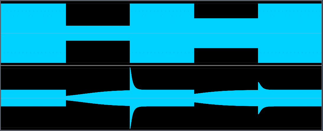
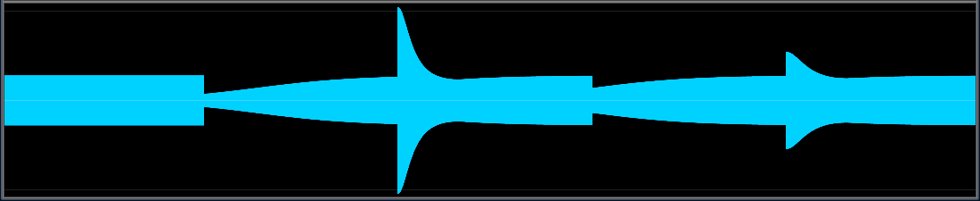
Standard behavior (input and output):
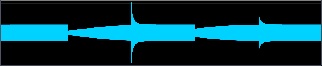
Too low Attack Shape will cause the attack to start later and go down too deep:
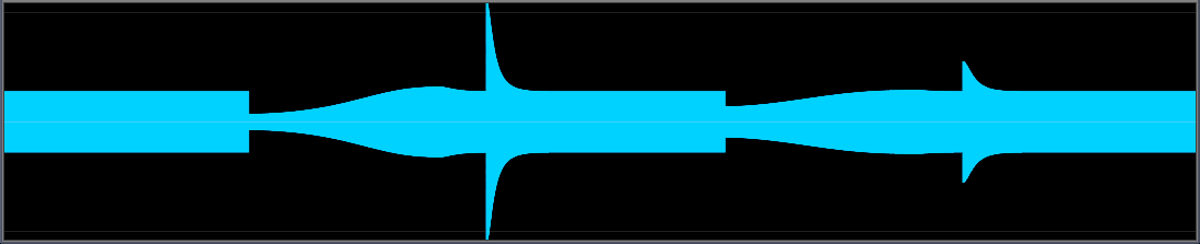
Too high Attack Shape will cause the attack to jump down instantly, but using a more asymptotical behavior - if you increase the Attack time to compensate, it will take very long before the target level is reached:
Exceed Max Attack Speed Allows exceeding Max Attack Speed if the input is very loud.
This is the automatic door behavior again: If you push very hard against a hydraulically controlled door, the oil in the hydraulic system starts to heat up, and as a consequence, the oil becomes thinner and the door will start moving faster. This setting controls how much faster the door can move if the pressure is high for a while (see also Exceed Attack Rise).
Exceed Attack Rise Determines how fast Exceed Max Attack Speed responds to a very loud input level.
In the hydraulic door example, this determines how fast the oil heats up.
Release section Release settings. Release panel
Release Time The time it takes for the output level to climb by 10 dB if the input level falls silent.
Auto Release Shape Automatically determines the optimal value for Release Shape.
Release Shape Determines the release behavior.
Attack Shape and release shape must be balanced to get good results. Normally, they are filled in automatically, but you can still change them to get a different behavior.
Standard behavior (input and output):
Too low Attack Shape will cause the attack to start later and go down too deep:
If you lower it even further the effect is even more extreme:
Too high Release Shape will cause the release have a more asymptotical behavior, it will take very long before the target level is reached:
Exceed Max Release Speed Allows exceeding Max Release Speed if the input level drops a lot.
Hydraulic door behavior: If you release the door it will close at a certain speed. In this case, if you were to put pressure on it to close faster, the oil in the hydraulic system warms up and becomes more fluid, which makes the door close a bit faster. This control determines how much faster the door can move if the pressure if high for a while (see also Exceed Release Rise).
Exceed Release Rise Determines how fast Exceed Max Release Speed responds to a very low input level.
In the hydraulic door example, this determines how fast the oil heats up.
Exponential Release Release faster if the input level drops more.
Release Gate section Gating settings for release.
If the current output is much softer than the target level, this stops release from acting. This helps for example to avoid releasing when there's only noise present, which would boost the noise. Also, for example during speech, if there's a moment of silence, this stops the compressor from releasing completely, which would cause the attack to get a very big spike that it needs to handle.
Gate freeze Level below which all release action stops.
If the output audio is below this level, release stops completely. Be careful with this, if it is set too high, it can cause the compressor to not come back after a big spike!
Gate slowdown If the input level is lower than this, release is slowed down.
Levels section Levels panel
Density Adjusts both Drive and Band mix to have more compression but the same average output level.
Threshold level Amplification of the input before the compressor/limiter.
Knee Makes the transition around the threshold more smooth.
At the threshold the response to slightly different input levels changes abruptly. Knee smooths the transition.
Band mix Output level of this band.
Use the Band Mix settings to increase or decrease the presence of frequency bands.
Limiters section Limiter settings. Limiters panel
Limit The maximum output level of the limiter.
Limit speed
Limit before compress Protects the compressor against big spikes which are limited anyway.
If this is enabled, if a sound will be limited, the compressor will act as if the signal is limited before entering the compressor. As a result, it will go down less fast on sudden loud sounds.
Sound section Sound panel
Feedback Chooses between feed forward and feedback mode.
In feed forward mode, the input is used directly for the measurement. In feedback mode, the output level is measured instead of the input level.
Feedback mode is known to sound more natural, but the level control is far less accurate. For example, say the input level is 6 dB too loud and the ratio is 1:1000. Then in feed forward mode, the level will be reduced by about 6 dB. But in feedback mode, once the level is reduced by about 3 dB, the compressor will 'see' that it needs about 3 dB of reduction and not reduce the level further.
Ratio Determines how strongly the compressor responds to changing input levels.
Say, at one moment a sound comes in at the threshold level, so nothing happens to it. If another sound comes in at 6 dB above the theshold level, the input should be reduced by half. The ratio indicates how much of the increase in input level is not removed. At a the lowest ratio (1:1), the compressor is basically disabled. At the maximum ratio, 1000:1, 1/1000th of the increase is kept.
Channel separation Process channels separately, combined, or in between.
At 0%, the two channels will always behave the same. At 100%, they move completely separate of each other.
Detection type Chooses between RMS or Peak level measurement.
Peak mode can cause quite large reactions to a single small spike in the sound. RMS mode responds more like human hearing does, but low frequencies seem to be counted a lot stronger than in peak mode, which easily causes pumping.
Peak mode
ITU-BS.1770
Lookahead Lookahead time.
This determines how much the compressor looks ahead. For fast attack speeds (under 10 ms), this helps a lot to remove the short spikes that remain after compressing.
Lowpass below Lowpasses the compressor control signal.
By lowpassing the control signal from the compressor, distortion from fast compressor action is removed. It also helps smoothe out remaining spikes when the Attack is a bit too slow, since the filtering works symetrically (not only forward in time).
Bands section Controls the number of multiband compressor bands. Bands panel Controls the number of multiband compressor bands.
Slope to {} Steepness of the left slope of the band.
Less steepness generally gives a more natural, but sometimes harder to control sound.
Flat tops The level at which the top of this band must be cut off.
If no compression/limiting occurs, or if all the bands are compressed/limited by the same amount, the end result is guarranteed to be flat in frequency response.
Slope from {} Slope of the right side of the band.
Less steepness in general gives a more natural, but harder to control sound.