AGC section The AGC filter attempts to make the audio level constant, without causing noticeable changes in the sound.
If does so by - if possible very gradually - increasing and decreasing the audio level. If sudden spikes are present, it can remove those spikes without lowering the output level too much, to avoid pumping and similar annoying effects.
The AGC never increases the incoming audio level, it only decreases it if it gets too loud. Use Pre amplifier to increase the input level.
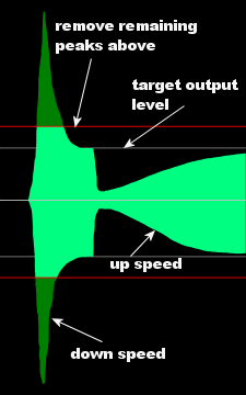
Before AGC
AGC output
Piece of audio before and after AGC. The output signal (bright green) is much more constant in volume than the input signal. Main panel Main AGC settings.
Enabled Enables the AGC.
AGC Target output level Determines the target maximum output level.
This is the input level for the next processing step, usually the Multiband Compressor.
Matrix panel Matrix mode lets the AGC work on Left+Right and Left-Right instead of Left and Right channels. (Experimental)
This makes the stereo signal very constant - and probably way too strong for most purposes. The output contains nearly the same amount of audio in L+R and L-R, which means that there's an extreme amount of stereo present, so it usually needs to be tamed down a bit afterwards. This mode is experimental and may have unwanted side effects.
You should probably disable Stereo Boost when you use this.
For FM, Matrix AGC without taming down the stereo tends to increase multipath distortion problems, if you're going to try this out, enable the Stokkemask filter to compensate for that. And tame the stereo down a bit, otherwise it's really too much.
Matrix mode (L+R / L-R) Enables the experimental Matrix mode.
Reduce stereo If set below 100%, reduces the effect of Matrix.
L+R to L-R channel mix Add a portion of L+R to the L-R channel for the volume measurements.
This reduces the amount of stereo increment if there's a big difference between L+R and L-R.
Instead of adding a portion of L+R to L-R, use the maximum of a portion of L+R and L-R. This reduces the maximum stereo increment.
Current levels panel Shows AGC activity.
General section General AGC settings. Gate panel Stops the volume from rising when there is (near) silence.
If the input level is very low (noise, silence), raising the output level might cause annoying effects (increasing noise levels during silence, followed by a sudden drop when the sound starts again). When using Gating, if the input level is below the configured Gating level, the gain rise is reduced or stopped (Band 1+2 upspeed and Band 3 upspeed are dynamically reduced).
Gating based on volume before Pre Amp Determines whether Gating is based on the actual input level, or the input level after Pre amplifier.
If this is enabled, the gating level is based on the input level, ignoring the setting of Pre amplifier. In other words, increasing Pre amplifier does not require changing the Gating level.
If this is disabled, gating just responds to the actual input volume of the AGC - if Pre amplifier is increased, the Gating level also needs to be increased to get the same behavior as before.
Gating level Stops the volume from rising when there is (near) silence.
If the input level is very low (noise, silence), raising the output level might cause annoying effects (increasing noise levels during silence, followed by a sudden drop when the sound starts again). This slider determines that if the input level is below the configured Gating level, the gain rise is reduced or stopped (Band 1+2 upspeed and Band 3 upspeed are dynamically reduced).
Spikes panel Handling of sudden burst of loud audio.
The AGC slowly adjusts the level to keep the average level constant. This section overrides the standard AGC behavior to immediately lower the level very rapidly if the volume suddenly increases a lot. Without this, the AGC output would in some cases still contain very loud audio.
Sudden volume jump protection: Threshold If the volume suddenly increases by more than this amount, sudden burst protection is activated.
If you set this level too low, sudden burst protection will be activated too soon and there will be a loss of dynamics. If it's set too high, loud bursts will be let through to the next processing steps. You can see that loud burst protection is active in the output meters - when burst protection is used a piece of the meters gets a different color.
The slope adjusts the size of the area in which more and more protection occurs.
Behavior panel Some specific settings to make the AGC work better.
Allow louder female voices Avoids AGC level drops caused by loud female voices in songs.
In some tracks with really loud female voices (for example, many Celene Dion songs), the AGC will lower the volume for loud notes, causing pumping. This setting detects such sounds and lowers them before adjusting the level.
This has been superseded by the much more powerful Side chain.
ITU-BS.1770 is the base upon which the R128 loudness level metering has been built. In ITU-BS.1770 mode, the AGC adjusts the level based on how human hearing works, instead of the actual power of the audio. Bass is counted less strong, and higher frequencies are counted stronger.
ITU-BS.1770 Head correction AGC responds more to high frequencies because they sound louder to humans.
ITU-BS.1770 Bass correction AGC responds less strong to bass because to human ears they seem to sound less loud.
BS412 panel Prepares the AGC for the BS412 levelling which is required for FM stations in some European countries.
Among others, stereo (L-R) sounds are treated as less important than mono (L+R) sounds, because in the BS412 level measurement that's also the case.
Prepare for BS412 if BS412 limiter enabled Turns BS412 preparation on.
Misc panel Some settings that normal users don't need.
Startup input level Sets the AGC level upon program startup.
For normal processing, it doesn't really matter where the AGC starts, but if you use Stereo Tool to master music for example, and you use Stereo Tool as a VST plugin, then you might want to be able to configure the start level of the AGC to avoid unwanted volume effects in the first few seconds after start of processing.
Up push strength near minimum reduction Lets the AGC move towards 0 dB (no action) faster when it gets close to it.
Bands section Select 1, 2 or 3 bands AGC.
[b]While the AGC offers upto 3 bands, since the Side chain was added, the best result can be obtained using only 1 band comgined with Side chain. The rest of the text is kept here to explain what the other settings do, but we strongly advise to use 1 band with Side chain.
1 band gives the best approach of the total RMS volume. However, loud bass sounds will cause other frequencies to be dropped (which makes sense, as they count as part of the RMS volume).
2 bands sounds more constant. Band 1 contains all the sound (hence behaves identical to the 1 band AGC), band 2 contains frequencies above 200 Hz. There are 2 issues when using 2 bands:
The volume of the two bands may move apart, causing the audio to sound different.
In the 2nd band, because very low frequencies are ignored, loud higher frequencies such as loud voices in music may cause the volume of band 2 to drop.
3 bands is identical to 2 bands (see the previous paragraph), except that very loud highs are reduced. This time, also the level of the 3rd band is never increased above that of band 2. Reduce band 3 further if its volume gets above is used to set the target maximum highs level. Bands panel
Bands Controls the content of each band.
Band 1+2 upspeed Determines how fast the volume level is increased when the output level is below the AGC Target output level.
When the output volume has been lowered due to too loud sounds, this slider determines how fast the output volume can be increased again. A higher value means that the average output level gets closer to the target level, but may also cause pumping. A low value may cause source material with big volume changes to come out too soft on average - and the quieter parts will stay very quiet.
Band 1+2 downspeed Determines how fast the volume level is decreased when the output level is below the AGC Target output level.
When the output volume would be louder than the set maximum AGC Target output level, this slider determines how fast the output volume is reduced. A higher value means that the average output level gets closer to the target level, but may also cause sudden volume drops when very short loud spikes occur. A low value may cause spikes to remain when the sound suddenly increases a lot. See Spikes (and also the no longer advised Remove remaining peaks above) for a solution for that.
Remove remaining peaks above Removes short volume spikes that remain at the end of the AGC processing.
Superseded by Spikes, use that instead for better results.
The AGC responds slowly to volume changes, to keep the effects on the audio as small as possible. This does mean that if the volume suddenly increases a lot, a loud 'spike' of sound can remain. This slider determines how much 'spike' is allowed above the configured Band 1+2 upspeed; anything louder than that is reduced.
If this slider is set too high, loud spikes remain; if it is set too low, too much spikes are removed, which takes out 'kicks' from the audio, making it sound too 'flat'.
If this setting causes peaks to be removed, black bars are displayed in the output bars at the bottom of the window. Ideally, these should only occur when they are needed (sudden volume jumps), not during 'normal' music (like every bass kick).
Compatibility & behavior panel Some recent improvements to the AGC behavior can be turned on or off here for compatibility.
Older presets that were made before these improvements were added still work as intended if these settings are kept off. For newer presets, it's a good idea to turn them on.
Originally, if the input volume dropped a lot there release could get incredably fast, especially if the AGC was at a very low level. This means that different input levels cause different AGC behavior, which is bad. Improved Release fixes this. The only reason that this setting is available is that older presets were made without this feature, and they still need to work properly.
Block size Adjust the RMS measurement block size.
With a smaller block size, staccato-sounds are better adjusted in level - the volume is lowered more (the silence is more or less ignored) which better corresponds to how human hearing works.
Band links section Configures linking between bands and channels. Stereo panel Configures linking between left and right channel.
Channel separation Determines how independent the two channel volumes can move.
If both AGC channels behave completely independent of each other, a loud tone on one channel may cause strange stereo effects because other tones are reduced on one channel, but not on the other. On top of that, the total audio content changes if this happens.
If both AGC channels do exactly the same, a loud tone on one channel causes volume drops on the other channel, which can also be unwanted.
This slider allows choosing an intermediate setting.
Combine remove remaining peaks channels Lowers both channels if one needs to be lowered by Remove remaining peaks above.
Without this, a drop on a single channel can sounds really bad, especially when listening to headphones.
Band links panel Links between bands.
Raise band 2 output level above band 1 if its volume drops below Configure band 2 protection against volume drops due to loud mid or high frequencies.
See Bands. This slider is used to tell the AGC how loud band 2 is expected to be compared to band 1. Band 2 is processed with a lower Target RMS level, based on this setting. Normally this should lead to roughly identical dynamic amplification levels for band 1 and 2. If - due to loud mid or high frequencies - band 2 is much louder than the configured level, its output volume is not dropped below the output volume of band 1. This means that, in cases where relatively loud mid or high frequencies are present, the 2 band AGC starts behaving more like a 1 band AGC, which gives better protection against unwanted volume drops and rises.
But never raise band 2 more than this above band 1 Configure band 2 protection against very loud highs relative to the lows.
See Bands. If there are only bass sounds present, the band 2 output level could rise indefinitely, while band 1 would be kept very low. This greatly increases noise levels. (For example, if the bass in the input is reduced by a factor 40, and the highs are not reduced at all, in total the highs are 40 times louder than the lows). This slider configures how much the band 2 output level can rise above the band 1 output level.
Keep band 1 at band 2 level if it stays less than this above band 2 Configures how much extra bass is needed to drop band 1 output level below band 2 output level.
See Bands. If the bass is just a bit too loud (the band 1 output level would drop slightly below the band 2 output level), keeping the band 1 output level equal to the band 2 output level gives much better results, because it better preserves the original audio content. But if the bass gets very loud, it does need to be dropped. This slider configures how much louder band 1 may get before its output level is reduced.
Reduce band 3 further if its volume gets above Configure the maximum high frequency RMS level.
See Bands. If 3 bands are used, this slider configures the maximum high frequency RMS level, relative to the AGC Target output level. Note that band 3 will never be louder than band 2, so setting this to 100% makes the 3 band AGC equal to the 2 band AGC. Setting it to 0% completely removes the highs.
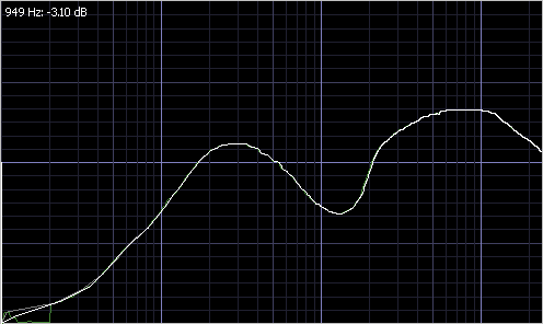
Side chain section Lets certain frequencies be counted more than others by the AGC. Side chain panel
PEQ Sidechain Lets certain frequencies be counted more than others by the AGC.
See for example this image:
As you can see, low bass frequencies are ignored. This means that in a track, if suddenly the bass kicks in, the level is hardly adjusted. Similarly, frequencies between 600 and 2000 Hz are counted a lot less strongly, which helps to keep the level constant for loud female voices. This avoids pumping.
Power Bass section Adds a lot of low end bass to (mostly older) tracks that lack such bass.
This results in a much deeper and warmer sound which is now present for both old and new music. On tracks that already have a lot of deep bass it has little effect. Power Bass panel The Power Bass settings.
Power Bass Enables Power Bass.
Maximum extra bass The maximum amount the low bass may be increased.
Bass frequency The frequency upto which Power Bass functions most strongly.
Slope (steepness) How fast the Power Bass response drops after the Bass frequency.
Ignore side chain Ignores any side chain for the Power Bass behavior.
In some cases, side chains have so much impact on the bass that Power Bass will always boost the bass, even when it's not needed at all. This setting should probably always be on (and will probably be removed in a future version).
Bass AGC (Old) section Should no longer be needed.
This was used to protect the clipper against too much bass, but with all the improvements to the multiband compressor, limiter and clipper and the introduction of Power Bass since Bass AGC was created, it should probably not be used anymore. Compressor section Singleband compressor locked to the AGC output.
Reduces the dynamic range of the audio and limits it.
Volume compression (A.K.A. audio level compression) reduces the dynamic range of a sound. This means that loud sounds become softer, and soft sounds become louder.
Limiting limits the maximum audio level below a certain threshold.
The compressors and limiters in Stereo Tool are protected against causing distortion. So very aggressive settings and large amounts of limiting can safely be used. General panel General compressor/limiter settings.
Enabled Turns the compressor/limiter on.
Quick adjust panel Achieve several effects with a single slider.
Most of these sliders impact the value of several other sliders that are described below, to achieve a certain effect.
Aggressiveness (hot) Makes attack and decay faster or slower. Sound is more squashed.
This slider adjusts both attack and decay to have more aggressive compression.
Speeds panel Attack, release and ratio.
These are standard settings that almost every compressor has.
Ratio Determines how strongly the compressor responds to changing input levels.
Say, at one moment a sound comes in at the threshold level, so nothing happens to it. If another sound comes in at 6 dB above the theshold level, the input should be reduced by half. The ratio indicates how much of the increase in input level is not removed. At a the lowest ratio (1:1), the compressor is basically disabled. At the maximum ratio, 1000:1, 1/1000th of the increase is kept.
Attack (time to drop 86%%) The time a 86% volume reduction due to a higher input level takes.
If the input level increases a bit, the volume goes down more slowly than if it increases a lot. This means that it's not possible to give a value in dB/ms.
Release (time to raise 10 dB) The time it takes for the output level to climb by 10 dB if the input level falls silent.
Release hold time Time for the 'brake' on the release to fade out.
When attack has been active, release is not immediately activated to avoid excessive movement. Instead, the release is held back for a while. This slider determines how long.
Gammas panel Settings that change the standard compressor behavior.
Attack Flatness Lets the compressor respond faster to small differences and slower to bigger ones.
Small differences in level are thus quickly compensated, with helps to reach the target level much faster. And the compressor attack responds less aggressively to big volume changes.
Release Flatness Lets the compressor respond faster to small differences and slower to large ones.
Small differences in level are quickly compensated, with helps to reach the target level much faster as long as differences in level are small. This gives a much more sparkling, 'alive', sound. But... Big differences are less quickly compensated. See Release Inertia for a solution for that.
Another explanation to further clarify things: In the compressors, if there's a volume change, it takes quite long for the level to 'stabilize'. That's because the closer the actual level gets to the 'target' level, the slower it moves (the shape is asymptotic). Something similar happens in release. This seems to be a good thing, and traditionally this is what compressors do.
What Flatness does is:
If the difference in level is 6 dB, nothing changes
If the difference in level is less than 6 dB, for Flatness values > 1 the change speed is increased.
If the difference in level is greater than 6 dB, for Flatness values > 1 the change speed is decreased.
More technical: The Flatness'th root of the difference in level is used - so for 2 that's the square root etc.
What this means: The higher the Flatness value is, the more the movement to the new level will look like a straight line instead of an asymptote.
Release Inertia Adjusts release behavior to match human hearing for more natural results.
Without Inertia and Release Flatness, after a very big volume spike the speed at which the audio returned was always the same - but determined by how much it had to move up. So, if the volume dropped by 6 dB and after 100 ms the volume went up 3 dB, then for a volume drop of 12 dB that would be 6 dB. Sounds perfect.
But it's not. Say you have a huge drop, for example after a very loud 'S' in the high frequency band, where normal volume differences are at most a few dB and this S suddenly sticks out 20 dB. For a difference of 4 dB, after 100 ms the difference in level is 1 dB - 75% of the difference is reduced. Now, this last 1 dB is really nearly unnoticeable, so for your ears the release kinda stops after 100 ms. But, for a difference of 20 dB, after 100 ms the difference is still 5 dB! And you need more than another 100 ms before you reach this 1 dB point.
So, after a loud sound you hear a gap at settings that sound good for small volume differences.
Release Flatness helps a lot for the final part of release: Small differences get compensated faster. But at the same time, bigger differences take longer to recover, which causes the same effect for really big differences as before.
Inertia fixes this. With inertia combined with Release Flatness you can make the release happen in a nearly constant time, without the slowdown at the end that you would have without Release Flatness, but also without the slower recovery for very big volume differences. Basically, the release happens in a nearly straight line, but the slope of the release depends on how much level must be compensated. With high Inertia values, release can even be faster for very big differences than for smaller ones, which can be good to quickly fill up the gap after a loud sound.
For bigger Gamma values you need bigger Inertia values.
In case things are not yet clear now, here's another explanation: For release, especially large differences must be compensated very fast - for 2 reasons:
Big differences mean very dynamic input, and for more dynamic input it's good that more compression occurs.
If you have a loud sound, and it takes multiple seconds for the level to get back, that sounds really bad.
Example:
Sound drops by 4 dB. When 3 dB has been restored, you really won't hear much difference anymore in level.
Sound drops by 40 dB. Now, when 39 dB has been restored you really don't hear much difference anymore.
So in one case when 75% restoration is there we're good, in the other we need 97.5%. And since - without Release Flatness - the behavior is asymptotic, reaching 97.5% takes multiple times as long as reaching 75%. Higher Release Flatness values only make things worse.
Why is this bad? Well, it makes it nearly impossible to find a good Release (time to raise 10 dB), what works well for small differences will be far too slow for big differences, and what works well for big differences will sound very aggressive on small differences.
So, the time it takes for the level to be restored to a level where human hearing stops to notice a difference - say 1 dB below the target level - must be nearly constant.
Inertia ('heavyness') makes sure that once release is moving up, the speed won't slow down until the target is reached. For big drops the effect is much bigger than for small drops, which is exactly what is needed.
Release Inertia and Release Flatness must be configured to work properly together. The best way to do this is to record a sample with different level tones (Loud - soft, loud - less soft, loud - just a little less loud), and check if all take approximate the same time to reach a level slightly below the target level.
Analogy
If you have to drive 10 meters, you just barely hit the gass and drive very slowly. If you have to drive 1 km, you hit the gass and speed up (Release hold time), then release the gass and let the car roll slowing down towards the end. With Inertia, you would not release the gas until you're very close to the end and then hit the brakes to stop.
Continuous Release The size of the area around the current sample used to calculate the RMS level.
Bigger values means less precise timing of attack/release behavior, but also less effect from low frequencies (less pumping). Generally, the RMS block size should be set just high enough to not cause distortion when using the limiters (Threshold level) a lot.
Levels panel Controls at which input level the compressor and limiter become active.
Threshold level relative to AGC The input level above which the compressor becomes active.
Knee Makes the transition around the threshold more smooth.
At the threshold the response to slightly different input levels changes abruptly. Knee smooths the transition.
Gate level If the input level is lower than this, release is slowed down.
Limit level The maximum output level of the limiter.
Limiter max release Controls the release behavior of the limiter.
The limiter attack is always as fast as possible without causing distortion. The same is true for release, but in some cases the release behavior can be too prudent. This slider overrides the standard limiter release behavior: If the release behavior that would be used based on the adaptive algorithm is slower than this, the configured release time is used instead. This does mean that very fast release times can cause some distortion.
Channel separation Process channels separately, combined, or in between.
At 0%, the two channels will always behave the same. At 100%, they move completely separate of each other.
Detection type Chooses between RMS or Peak level measurement.
Peak mode can cause quite large reactions to a single small spike in the sound. RMS mode responds more like human hearing does, but low frequencies seem to be counted a lot stronger than in peak mode, which easily causes pumping.
Feedback Chooses between feed forward and feedback mode.
In feed forward mode (0%), the input is used directly for the measurement. In feedback mode (100%), the output level is measured instead of the input level.
Feedback mode is known to sound more natural, but the level control is far less accurate. For example, say the input level is 6 dB too loud and the ratio is 1:1000. Then in feed forward mode, the level will be reduced by about 6 dB. But in feedback mode, once the level is reduced by about 3 dB, the compressor will 'see' that it needs about 3 dB of reduction and not reduce the level further.
Look-ahead time Lets the compresor respond to the sound a bit in the future.
This means that the initial spike of a loud sound gets reduced better, which can give a more natural sound.
The attack of the limiter is already protected, and if you don't use very short attack times for the compressor this probably has little effect.
Limiter distortion Allows the limiter attack to distort.
Some people like this effect, especially on low frequency audio - bass kicks get a special type of 'edge'.
Non-standard attack panel Protection against spikes for slow compressor settings.
Some presets use very slow attack and release times. This can sound great, but the level control for sudden volume increases is less good.
This section contains the settings for an extra compressor that takes over in such cases. It does not affect normal audio.
Level difference Increases the level of the 2nd compressor with faster attack.
Because the attack is so much faster, the audio level of the 2nd compressor is generally a bit lower. If we would take the minimum of the two, we would always look at the 2nd compressor, but that should only happen in extreme cases. By increasing the output level and then taking the maximum of the two, the 2nd compressor only has an effect on the sound if its output level is quite a bit lower. For example, if this value is set to 2.00, the 2nd compressor will not kick in if the level difference is less than 6 dB.
Minimum drop Disables the 2nd compressor if the attenuation didn't suddenly drop a lot.
The 2nd compressor should only be active if there's a huge difference between the volume when using a normal and very fast attack, but that's not all - if you play very dynamic music it should not kill the punch. This slider controls how much the attenuation must have suddenly dropped (in the fast attack 2nd compressor) for it to be taken into account.
Fast Attack The fast attack time.
To be useful, this must be a lot smaller than Attack (time to drop 86%%) - typical values are around 1-5 ms.
Release speedup Controls how much faster the 2nd compressor release is.
Beside a faster attack, the release for the 2nd compressor can also be made faster. This helps to prevent long-term volume drops after a short loud spike in the sound. This value controls how much faster the release is than Release (time to raise 10 dB).
Non-standard release panel Experimental settings. Should probably not be used.
Dynamic release Dynamically increase the release speed if the volume drops more.
If this is set to 0 the release always runs at exactly the same speed. A similar effect can be reached with Release Flatness.
Dynamic release to 0 dB Release acts as if the input level is always at 0 dB.
So the release speed depends only on how deep the level has dropped. See also Continuous Release.
Non-standard tweaks panel Settings that control compressor/limiter envelope detection.
In a compressor we have 2 things: An 'envelope', basically a line that follows the audio level, and the compressor behavior itself. If the level drops a lot, release is faster - and this is based on the envelope. Now, if the envelope just follows sample levels, then there will be a lot of near-0 values (just when a waveform crosses 0) which would cause infinitely fast release behavior. The envelope line needs to be made such that this doesn't happen.
So, around a peak in the waveform, for the surrounding samples we should not allow the envelope to reach much lower values than the value of that peak.
That works fine for high frequencies. But if you take a bass, the sample values are dropping slowly and in the valleys the level will still approach 0. Which still causes issues with release behavior. Because of that, there's some code that measures DC offset and increases the Base smoothing to something close to infinity when there's more DC offset present. Base smoothing controls how big the area is that's considered for DC measurement (lower frequency = bigger area). What we are actually measuring here is DC offset in a specific direction divided by total (absolute) power.
RMS block size The size of the area around the current sample used to calculate the RMS level.
Bigger values means less precise timing of attack/release behavior, but also less effect from low frequencies (less pumping). Generally, the RMS block size should be set just high enough to not cause distortion when using the limiters (Threshold level) a lot.
Peak smoothing Controls envelope smoothing around peaks in the waveform.
Lower values may cause distortion, but too high values reduce the precision of the limiters and (to a much lesser extent) the compressor release behavior.
Bass detection Controls upto which frequency bass should be detected for Smooth Bass power.